03 Sep 2019 Process development for flux-free soldering with preforms (Part 2)
In part 2 of the article series “Process development for flux-free soldering”, we deal with the solder alloy and the effective temperature of the reducing agent.
Solder alloy
Choosing a suitable solder alloys is crucial for the success of the product. The following boundary conditions should be considered:
- Price
- Melting temperature: Eutectic or melting range
- Wetting behavior
- Likelihood of shrinkage voids
- Temperature dependent material properties (Young’s modulus, yield strength, creep properties)
- Intermetallic compounds (IMC)
- Lifetime / temperature cycling properties
- Legislation (e.g. RoHS and the ban of lead)
- Necessary storage conditions
- Shelf life on air
- Processability (e.g. for pick&place)
- Interaction with bonding agents
Depending on the melting point or range of the alloy, the solder profile peak temperature will be defined. For a solder with a melting range it is important to decide whether all alloying elements should become liquid. This will be determined from the requirements on cycle time, lifetime and maximum temperature for the devices.
The wetting behavior (wettability) is critical for the requirements on material quality of the joining partners as well as the soaking time and necessary concentration of the reducing agent. While lead solders have a good wettability, lead-free solders with tin are more challenging to achieve a good wetting.
Solder alloys with a melting range tend to have shrinkage voids more often than eutectic solders. But the volume shrinkage depends on the alloy.
The temperature dependent material properties impact the lifetime and temperature cycling capability. For analytical lifetime calculators and the Finite element method (FEM) the material properties are needed. For precise and comparable calculations, the boundary conditions of the material properties must be considered. This includes the testing method, parameters, test specimen, number of samples.
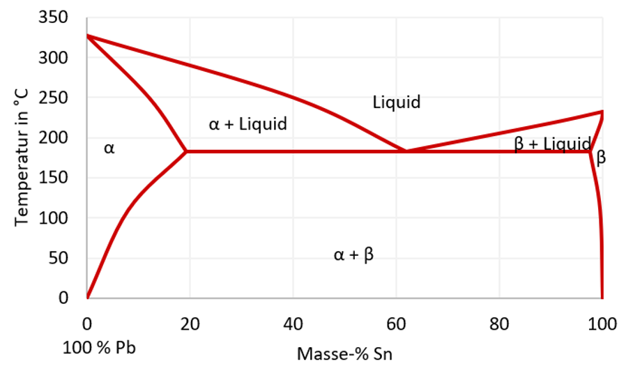
The formation of intermetallic compounds (IMC) depend on various boundary conditions and also has a direct influence on the lifetime of the product due to a very different material behavior of IMCs compared to solder bulk material. Determining factors are the temperature profile, the solder joint surfaces as well as the solder alloy. Phase diagrams can help to estimate the formation of intermetallic bonding. Figure 1 shows an example of a phase diagram.
For the soldering process the time above liquidus and cooling speed play a significant role. The duration that the solder is in liquid form influences the IMC growth. The cooling speed on the other hand affects the grains and microstructure of the solder layer. The lifetime and temperature cycling capability depend on both the grain structure and intermetallic compounds. At an eutectic composition (e.g. 63% Pb and 37% Sn) the solder solidifies directly at the eutectic line (183°C). Instead, at 30 weight-% Sn a melting range between 260°C and 183°C is created. During cooling down, a solid α-phase occurs first while lead is still liquid. At 183°C the complete solder becomes solid. Depending on the target application and boundary conditions, the flux-free soldering can melt the solder completely or just some alloy elements. This can be necessary when the maximum temperature is limited due to electrical components.

Figure 1: Phase diagram of tin (Sn) and lead (Pb)
The necessary storage conditions are solely relevant for preforms or nickel-coated devices. Preforms should always be stored in a dry cabinet. Some devices require special conditions such as inert gas atmosphere with nitrogen or helium. The increase in costs for the storage must be considered as well.
The shelf life of preforms is another factor to consider when choosing the right alloy. Some solders can only be stored on normal air for 20 minutes. After this time the oxide layer has grown significantly and the reducing agent can no longer completely remove the oxides.
The processability (e.g. with pick&place machines) should be considered as well. This includes the optical recognition and mechanical handling.
To avoid positioning failures of preforms and dies, bonding agents are used. Interactions and the impact of possible residues must be examined.
Reduction agent operation temperature
For the development of the flux-free solder profile, the most effective operating temperature of the reduction agent must be taken into consideration. Table 3 shows a comparison of the most commonly used reduction agents.
Further links:
- Process development for flux-free soldering with preforms (Part 1)
- Process development for flux-free soldering with preforms (Part 3)
- Process development for flux-free soldering with preforms (Part 4)
- Vacuum soldering is like an award winning cousine
- Trainings on vacuum soldering
- Fast Troubleshooting for Soldering Production Downtimes and Quality Issues
- Support for Research and Development of Vacuum Soldering Processes
- Soldering Process Improvement
Do you have further questions about vacuum soldering? Then feel free to contact us.

